Exceeding Expectations
 Distance SensorA novel LVDT used for measuring distance--similar to digital calipers. |  Iron CoreThe iron core is a crucial component for increasing the coupling between inductors. |  Aluminum RodAluminum was used to connect to the iron core because it will not influence the coupling between the inductors. |
|---|---|---|
 Inductors v1I used 21 gauge wire the to make inductors the first time. This didn't have a high enough inductance to make a useful signal. |  Inductors v2The second attempt at making inductors succeeded and made a much larger signal. 33 gauge wire was used this time. |  33 GaugeAbout 500 windings of 33 Gauge wire was wrapped around a straw -- twice. It was not the most exciting part of the project. |
 BreadboardA circuit was constructed to create an isolated signal to put through the LVDT. | 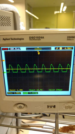 Peak DetectorThis is the of our LVDT circuit. The green line is the signal before our peak detector and the yellow is the signal after our peak detector. This was later fine tuned. |  Finalized DesignThe design was finalized, but not yet complete |
 CalibrationThe LVDT was calibrated using a 123 block (1"x2"x3") |  Success!This is the reading on our LVDT. 50.80 is exactly what we want to see. 2" = 50.80 centimeters |
LVDT Distance Sensor
2016
This was a school project where we were tasked with making a sensor to measure distance. A lot of teams decided to make an encoder. Me and my group members like to aim high, so we tried to make a Linear Variable Differential Transformer. Nobody has ever successfully completed this sensor in our course. In fact, our professor expected that we would need a lot of external parts or IC's to make this work.
Needless to say, we completed the sensor and it worked beautifully. The professor was impressed and we were ready to fall over from a lack of sleep; but, we did it.
This LVDT does not work like an ordinary LVDT which uses three inductors; this only uses two inductors and it relies on the fact that as the iron core moves inside the inductors, the coupling between inductors is increased.
We start off by generating a signal with a 555 timer and filter it until it's a sinusoide. Then amplify it and pass it through an isolation transformer to separate the loading effect due to the variable inductor. The isolation transformer passes the signal to one of the main inductors. The signal then hops over to the second inductor through magnetic coupling and we direct the wave to a peak detector so we have a DC form which our microcontroller can read.